Taskflow  3.2.0-Master-Branch
Loading...
Searching...
No Matches
Graph Processing Pipeline

We study a graph processing pipeline that propagates a sequence of linearly dependent tasks over a dependency graph. In this particular workload, we will learn how to transform task graph parallelism into pipeline parallelism.

Formulate the Graph Processing Pipeline Problem

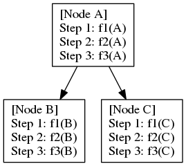
Given a directed acyclic graph (DAG), where each node encapsulates a sequence of linearly dependent tasks, namely stage tasks, and each edge represents a dependency between two tasks at the same stages of adjacent nodes. For example, assuming fi(u) represents the ith-stage task of node u, a dependency from u to v requires fi(u) to run before fi(v). The following figures shows an example of three stage tasks in a DAG of three nodes (A, B, and C) and two dependencies (A->B and A->C):

dot_graph_pipeline_1.png

While we can directly create a taskflow for the DAG (i.e., each task in the taskflow runs f1, f2, and f3 sequentially), we can describe the parallelism as a three-stage pipeline that propagates a topological order of the DAG through three stage tasks. Consider a valid topological order of this DAG, A, B, C, its pipeline parallelism can be illustrated in the following figure:

dot_graph_pipeline_2.png

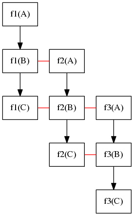
At the beginning, f1(A) runs first. When f1(A) completes, it moves on to f2(A) and, meanwhile, f1(B) can start to run together with f2(A), and so on so forth. The straight line represents two parallel tasks that can overlap in time in the pipeline. For example, f3(A), f2(B), and f1(C) can run simultaneously. The following figures shows the task dependency graph of this pipeline workload:

dot_graph_pipeline_3.png

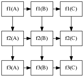
As we can see, tasks in diagonal lines (lower-left to upper-right) can run in parallel. This type of parallelism is also referred to as wavefront parallelism, which sweeps parallel elements in a diagonal direction.

Note
Depending on the graph size and the number of stage tasks, task graph parallelism and pipeline parallelism can bring very different performance results. For example, a small graph will a long chain of stage tasks may perform better with pipeline parallelism than task graph parallelism, and vice versa.

Create a Graph Processing Pipeline

Using the example from the previous section, we create a three-stage pipeline that encapsulates the three stage tasks (f1, f2, f3) in three pipes. By finding a topological order of the graph, we can transform the node dependency into a sequence of linearly dependent data tokens to feed into the pipeline. The overall implementation is shown below:

// 1st-stage function
void f1(const std::string& node) {
printf("f1(%s)\n", node.c_str());
}
// 2nd-stage function
void f2(const std::string& node) {
printf("f2(%s)\n", node.c_str());
}
// 3rd-stage function
void f3(const std::string& node) {
printf("f3(%s)\n", node.c_str());
}
int main() {
tf::Taskflow taskflow("graph processing pipeline");
tf::Executor executor;
const size_t num_lines = 2;
// a topological order of the graph
// |-> B
// A--|
// |-> C
const std::vector<std::string> nodes = {"A", "B", "C"};
// the pipeline consists of three serial pipes
// and up to two concurrent scheduling tokens
tf::Pipeline pl(num_lines,
// first pipe calls f1
if(pf.token() == nodes.size()) {
pf.stop();
}
else {
f1(nodes[pf.token()]);
}
}},
// second pipe calls f2
f2(nodes[pf.token()]);
}},
// third pipe calls f3
f3(nodes[pf.token()]);
}}
);
// build the pipeline graph using composition
tf::Task init = taskflow.emplace([](){ std::cout << "ready\n"; })
.name("starting pipeline");
tf::Task task = taskflow.composed_of(pl)
.name("pipeline");
tf::Task stop = taskflow.emplace([](){ std::cout << "stopped\n"; })
.name("pipeline stopped");
// create task dependency
init.precede(task);
task.precede(stop);
// dump the pipeline graph structure (with composition)
taskflow.dump(std::cout);
// run the pipeline
executor.run(taskflow).wait();
return 0;
}
class to create an executor for running a taskflow graph
Definition executor.hpp:50
tf::Future< void > run(Taskflow &taskflow)
runs a taskflow once
Definition executor.hpp:1573
class to create a pipe object for a pipeline stage
Definition pipeline.hpp:136
class to create a pipeflow object used by the pipe callable
Definition pipeline.hpp:42
class to create a pipeline scheduling framework
Definition pipeline.hpp:312
class to create a task handle over a node in a taskflow graph
Definition task.hpp:187
const std::string & name() const
queries the name of the task
Definition task.hpp:499
void dump(std::ostream &ostream) const
dumps the task through an output stream
Definition task.hpp:573
Task & precede(Ts &&... tasks)
adds precedence links from this to other tasks
Definition task.hpp:420
Task & composed_of(T &object)
creates a module task from a taskflow
Definition task.hpp:436
class to create a taskflow object
Definition core/taskflow.hpp:73
@ SERIAL
serial type
pipeline include file
main taskflow include file

Find a Topological Order of the Graph

The first step is to find a valid topological order of the graph, such that we can transform the graph dependency into a linear sequence. In this example, we simply hard-code it:

const std::vector<std::string> nodes = {"A", "B", "C"};

Define the Stage Function

This particular workload does not propagate data directly through the pipeline. In most situations, data is directly stored in a custom graph data structure, and the stage function will just need to know which node to process. For demo's sake, we simply output a message to show which stage function is processing which node:

// 1st-stage function
void f1(const std::string& node) {
printf("f1(%s)\n", node.c_str());
}
// 2nd-stage function
void f2(const std::string& node) {
printf("f2(%s)\n", node.c_str());
}
// 3rd-stage function
void f3(const std::string& node) {
printf("f3(%s)\n", node.c_str());
}
Note
A key advantage of Taskflow's pipeline programming model is that we do not provide any data abstraction but give users full control over data management, which is typically application-dependent. In an application like this graph processing pipeline, data is managed in a global custom graph data structure, and any data abstraction provided by the library can become a unnecessary overhead.

Define the Pipes

The pipe structure is straightforward. Each pipe encapsulates the corresponding stage function and passes the node into the function argument. The first pipe will cease the pipeline scheduling when it has processed all nodes. To identify which node is being processed at a running pipe, we use tf::Pipeflow::token to find the index:

// first pipe calls f1
if(pf.token() == nodes.size()) {
pf.stop();
}
else {
f1(nodes[pf.token()]);
}
}},
// second pipe calls f2
f2(nodes[pf.token()]);
}},
// third pipe calls f3
f3(nodes[pf.token()]);
}}

Define the Task Graph

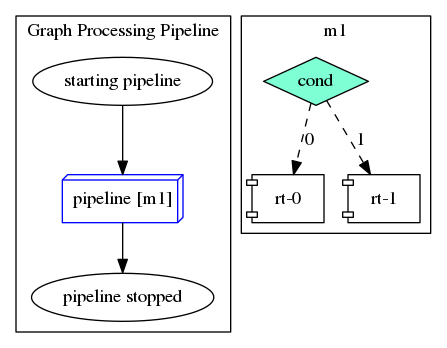
To build up the taskflow for the pipeline, we create a module task with the defined pipeline structure and connect it with two tasks that output helper messages before and after the pipeline:

tf::Task init = taskflow.emplace([](){ std::cout << "ready\n"; })
.name("starting pipeline");
tf::Task task = taskflow.composed_of(pl)
.name("pipeline");
tf::Task stop = taskflow.emplace([](){ std::cout << "stopped\n"; })
.name("pipeline stopped");
init.precede(task);
task.precede(stop);
dot_graph_pipeline_4.png

Submit the Task Graph

Finally, we submit the taskflow to the execution and run it once:

executor.run(taskflow).wait();

Three possible outputs are shown below:

# possible output 1
ready
f1(A)
f2(A)
f1(B)
f2(B)
f3(A)
f1(C)
f2(C)
f3(B)
f3(C)
stopped
# possible output 2
f1(A)
f2(A)
f3(A)
f1(B)
f2(B)
f3(B)
f1(C)
f2(C)
f3(C)
stopped
# possible output 3
ready
f1(A)
f2(A)
f3(A)
f1(B)
f2(B)
f1(C)
f2(C)
f3(B)
f3(C)
stopped